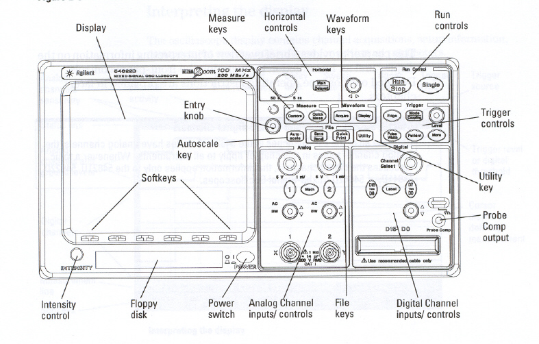
AGILENT 54622D MIXED-SIGNAL OSCILLOSCOPE

PROCEDURE TO SETUP MENUS
*NOTE* - Make sure that neither A1 or A2 are selected. Both
keys should not have the Green lights on.
- Press the D7 Thru D0 Key in the Digital/
Channel Inputs/Controls menu. The lower 8 digital channels will appear on
the screen.
You will notice that there are Five Soft Keys ;
- The First Soft Key represents the individual channel
.
The First Soft Key is used to select and unselect the
individual channels.Use the Entry Knob to move through all the
channels. By rotating the Entry Knob channels D0 to D7 appear on the
screen. Keep rotating the Entry Knob until you select the channel you
want,then stop . The channel select screen will go away after a few seconds.
- The Second Soft Key is used to select or unselect D7 Thru
D0 channels instead of individually selecting and unselecting the
channels.
- The Third Soft Key is used to scale the channels.By
pressing the Third Soft Key you will notice that the channels
are compressed closer together. This feature comes in handy if you want to
display more channels on the screen.
- By default the mixed signal scope is setup to display eight channels. To
display more then 8 channels do the following.
- using the Third Soft Key select the middle scale setting.
- using the channel select Knob select D0.
- using the D15-D0 Knob move D0 to the top of screen.
Continue doing this for all the other channels so that D0 Thru D7 are
all in the top half of the screen.
- Press the D15 Thru D8 key. This will give you 16 channels.
- *NOTE* You cannot display 16 channels in full scale. Only 8
channels can be displayed in full scale.
- TheFourth Soft Key selects the different voltage
thresholds
- TTL (1.4 v) [default]
- CMOS (2.5 v)
- ECL (-1.3 v)
- USER
- The Fifth Soft Key is used to program a user defined
Threshold voltage. This key is only active when USER is selected by
the Fourth Soft Key.
- Press the Label Key in the Digital Channel
Inputs/Controls menu.
The lower 8 digital channels will appear on the
screen.
You will notice that their are six Soft Keys;
- The First Soft Key represents the individual channel
.
The First Soft Key is used to select the individual
channels.You can also use the Entry Knob to select the channels.
Press the First Soft Key, all the channels appear on the
screen. Keep pressing the First Soft Key until you select the
channel you want,then stop pressing the Key . The channel select screen will
go away after a few seconds.
- The Second and Third Soft Keys are used to spell and enter
the label names. Press the Second Soft Key , then scrolling
with the Entry Knob. This allows you to select letters,numbers and
symbols from a list that appears on a window. Once you have selected the
character you want use the Third Soft Key to enter that value.
You will notice that value appear in the New Label = window.
- The Third Soft Key is also used to select all the
characters in the new label = window. By continually pressing the
Third Soft Key you scroll through all the characters in the
New Label = window.
- The Fourth Soft Key deletes the hi-lighted character.
- The Fifth Soft Key saves the New label = window to
the Save Label = window. This then becomes the new name for the
selected channel at the First Soft Key.
- The Sixth Soft Key is a library of saved label names. This
can be advantageous since it allows you to select names from an accumulated
list rather then have to spell them.
- If the Label Key is lit Green then the label names
should appear beside the channels. Press the Label Key till the
Green light is off. You will notice that the label names disappear.
When the Label Key is lit Green it should look similar Figure
1. It is possible that the label names may be different then below depending
on whether someone has already renamed the labels.
0 bit0
__________________________________________
1 bit0
__________________________________________
2 bit0
__________________________________________
3 bit0
__________________________________________
4 bit0
__________________________________________
5 bit0
__________________________________________
6 bit0
__________________________________________
7 bit0
__________________________________________
Figure 1
How to RENAME each CHANNEL
- Select the Label Key in the Digital Channel
Inputs/Controls menu.
- Select the First Soft Key Channel
- Turn the Entry Knob. Turning the Entry Knob scrolls through
the channels. Stop at the channel you want to edit the label name.
- Select the Second Soft Key Spell .
- Turn the Entry Knob. Turning the Entry Knob scrolls through
the letters,numbers or symbols in the Character window.
- Stop at the letter,number or Symbol you want.
- Press Third Soft Key Enter
- The letter,number or symbol appears in the New Label = window.
- By continually pressing Third Soft Key you select all the
characters in the New Label = window.
- Once the label name is edited press the Fifth Soft Key. This
will save the label name to the Saved Label = window.
- This will also become the name of the channel that was selected by the
First Soft Key .
- To change other channel names follow the steps just described.
Examples of Assigning Label Names
PREDEFINED NAME (R/W_ on Channel D5):
- Press the Label Key .
- Press the First Soft Key, then use the Entry Knob to
select Channel D5
- Press the Sixth Soft Key Library .
- Turn the Entry Knob until R/W_ appears in the New Label
= Window, then stop. The library window will disappear in a few seconds.
- Press the Fifth Soft KEY Save New
Label. The label name R/W_ will now appear in the Saved
Label = window.
- Now Channel D5 has the new label name
R/W_.
UNIQUE NAME (BRL on Channel D4):
- Press the First Soft Key, then use the Entry Knob to
select Channel D4
- Press Second Soft Key Spell.
- Using the Entry Knob rotate until B appears in the New
Label = window.
- Press the Third Soft Key Enter. The
prompt in the New label = window will move over one position.
- Repeat the above two steps for the letters RL.
- Use the Fourth Soft Key Delete
Character to get rid of any unwanted characters.
- Press the Fifth Soft KEY Save Label
Name
- The label name BRL will appear in the Saved Label = window.
- Now Channel D4 has the new label name BRL.
- Continue to use this technique to rename any of the channel Label
Names
Setting up a trigger Value
- Press the Pattern Key in the Trigger
menu.
- Another set of Soft Key Menus will appear.
- Press the First Soft Key Channel,
then use the Entry Knob to select a channel.
The channel label
name appears in the Channel window.
- Second Soft Key selects active low trigger event.
- Third Soft Key selects active high trigger event.
- Fourth Soft Key selects done care.
- Fifth Soft Key selects active rising edge trigger
event.
- Sixth Soft Key selects active falling edge trigger
event.
- Above the Pattern Select there is an expression;
Pattern = 1xx2 D15xxxx xxxx xxxx xxxx D0
- 1xx2 represent the trigger setting for Analog Channels
1 and 2.
For most of the applications in the lab we ignore
analog triggering so leave these two channels as Don't Care
"X".
- D15xxxx xxxx xxxx xxxxD0 represent each of the digital
channels D0 - D15.
- Scroll through the digital channels using the Entry Knob
The
channel beside the check mark can be changed to any of the trigger
values;
[ L,H,Rising Edge,Falling Edge ]
Example of setting up a Trigger
event
For this example do the following:
Change the channel label names as shown
below;
	0 Bit0 -------> CLK
	1 Bit0 -------> DTACK
	2 Bit0 -------> AS
	3 Bit0 -------> UDS
	4 Bit0 -------> LDS
	5 Bit0 -------> R/W
	6 Bit0 -------> A23
	7 Bit0 -------> A22
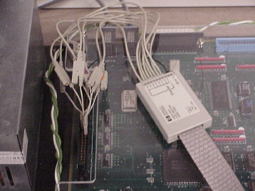
With POWER OFF connect the probe leads to the
ULTRA GIZMO M68000_BUS.
This is the 60 pin header found
above the 2 audio connectors on the left side of the board.
*NOTE*
When counting, pins on the left side of the header are odd number values and
pins on the right side of the header are even. 1 2
3 4
5 6
. .
. .
. .
59 60
(probe) (M68000_BUS)
--------------------------------
GND BLACK LEAD pin 1
0 CHANNEL 0 pin 2
1 CHANNEL 1 Pin 28
2 CHANNEL 2 Pin 30
3 CHANNEL 3 Pin 32
4 CHANNEL 4 Pin 34
5 CHANNEL 5 Pin 27
6 CHANNEL 6 Pin 26
7 CHANNEL 7 Pin 25
The connections should look like the picture below

Power up the ULTRA GIZMO Board.
Press the Reset switch on the ULTRA GIZMO Board.
Select the Pattern Key in the Trigger
menu.
Using the Entry Knob, scroll until UDS is
hi-lited.
Press the Fifth Soft Key, Trigger on rising edge
Select the SINGLE Key in the Trigger menu.
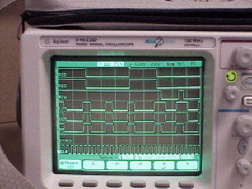
The screen should appear similar to the one below.

Use the Horizontal Control knobs to get a more
detailed view of the signals.
As the knob is rotated right the time per division becomes smaller but the
display becomes more detailed.
As the knob is rotated left the time per division becomes greater and more
signal information appears on the screen.
Now hook up your circuit and try to display signal information on the logic
Analyzer
TOP


